Posts

Temperature sensor (LM35) and Fan speed Controller using PIC16F877A

Image
Temperature sensor (LM35) and Fan speed Controller using PIC16F877A: This post provides a simple digital Temperature meter  circuit  using PIC16f877A microcontroller. This code is written in C language using MPLAB X IDE with XC8 compiler.  In this post, it is assumed that you know, How to use PWM in PIC16F877A microcontroller.  How to interface LCD with PIC16F877A microcontroller. Circuit : Figure 1: PIC16F877A based Fan speed Controller and Temperature meter Code : Figure 2 :Mikroc code for Fan controller Downloads: coming soon...

SMART WATCH TEARDOWN

Image
  SMART WATCH TEARDOWN Smartwatches have become an important part of our daily lives. They help us track our fitness, receive notifications, and even make calls. But have you ever wondered what is inside a smartwatch? In this blog, we will take apart a smartwatch to see its internal components. We will explore the display, battery, sensors, processor, and other key parts. This teardown will help us understand how a smartwatch works and how all the small components fit together in a compact design. Let’s begin the teardown and discover the technology inside a smartwatch! Before Opening Here’s a breakdown of the components: Battery (LQ-S1)  – This is a 3.7V, 380mAh rechargeable lithium battery. It powers the smartwatch and is designed for low-power operation. Main Circuit Board (PCB)  – This green board contains the key electronic components. 1: VIBRATION MOTOR 2: SPEAKER 3: PCB ANTENNA 4: MINI USB CONNECTOR 5: BATTERY CONNECTOR 6: SIM SLOT 7: CAMERA 8: SD CARD SLOT 9: POWE...

Automotive Ethernet Interface Basics

Image
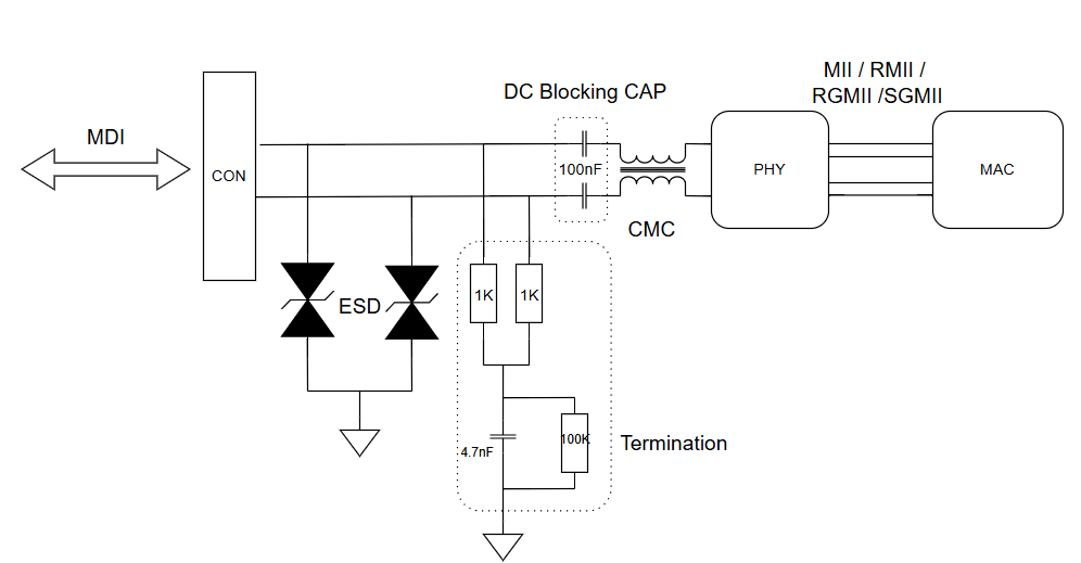
  Automotive Ethernet Interface Basics: In this article, we’ll revisit how Automotive Ethernet interfaces work and provide an overview of its various types, highlighting their key differences and applications. BLOCK DIAGRAM : Image Reference OPEN Alliance MDI (Media Dependent Interface):  MDI defines how signals are transmitted and received over Ethernet cables, especially in automotive networks using Single-Pair Ethernet PHY (Physical Layer) Chip : The signal from the PHY chip is transmitted over twisted-pair cables. DC Blocking / AC Coupling Capacitor : Placed in series between the PHY and the Ethernet cable to block any DC bias and protect the system. AC Coupling is realized by 100nF Coupling Capacitor to form a high pass filter together with 50Ohm termination on each line. Signal Integrity : The capacitor ensures that only the desired AC signal (which carries data) is passed to the PHY, while any DC bias is blocked. CMC (Common Mode Choke) is used to reduce electromagneti...

Exploring USB Device Detection with Arduino and USB Host Shield

Image
  Exploring USB Device Detection with Arduino and USB Host Shield USB (Universal Serial Bus) is a ubiquitous interface for connecting peripherals to computers and other devices. Arduino, with its versatility and expandability, can be used to interface with USB devices using a USB Host Shield. In this article, we'll explore how to detect and identify USB devices connected to an Arduino using a USB Host Shield. Hardware Used: Hardware Description Arduino Board Any compatible Arduino board with sufficient GPIO pins and USB Host Shield library support. USB Host Shield A shield specifically designed for USB host functionality, compatible with the selected Arduino board. USB Devices Various USB peripherals like mass storage devices, input devices (keyboard, mouse), communication devices, etc. Serial Monitor A computer running Arduino IDE or any other serial terminal software for monitoring the Arduino's serial output. Power Supply Depending on the connected USB devices and Arduino bo...

MI TV Remote Teardown

Image
MI TV Remote Teardown This MI remote uses Bluetooth low energy SOC from Realtek ( RTL8762C) The RTL8762A supports an analog MIC interface that integrates a sigma-delta ADC, programmable gain amplifier, 5-Band equalizer and microphone bias circuit for voice command application.  RTL8762AR General Ultra low power consumption with intelligent PMU Supports Bluetooth 4.2 core specification Integrated MCU to execute Bluetooth protocol stack Supports multiple level Low Energy states Supports LE L2CAP Connection Oriented Channel Support Supports LE low duty directed advertising Supports LE data length extension feature Supports OTA (Over-the-Air) programming mechanism for firmware upgrade Supports external 32KHz XTAL for low power mode Supports GAP, ATT/GATT, SMP, L2CAP Generic Applications for GAP Central, Peripheral, Observer and Broadcaster Roles   Platform ARM® Cortex™-M0 (Maximum 53MHz) 256KB embedded flash 80KB RAM 2KB eFUSE Supports AES128/192/256 encrypt/decrypt engine Bluetoo...

Interfacing of PIC16F877A with LCD in 4 bit mode

Image
This post provides the code for interfacing the PIC16F877A microcontroller with LCD in 4bit mode.   This code is written in C language using MPLAB with XC8 compiler. The following diagram (made in  Proteus ) shows the PIC microcontroller circuit diagram.   Figure 1 .   PIC16F877A 4bit  LCD interfacing circuit Code: Figure 2 .   The main function for interfacing LCD with PIC16F877A In the main function, firstly LCD is initialized in 4-bit mode using  InitLCD()  function. After that, LCD screen is cleared using  ClearLCDScreen()  function. Then ' Hello !'  is written on the first line 0th position of the LCD screen and "World" is  written on the Second line 5th position of the LCD screen .  Actual circuit output: Figure 3 .   PIC16F877A + 16x2 LCE in 4bit mode operation output Downloads 4 bit LCD interfacing code using PIC16F877A was compiled in MPLAB X V54.45 IDE with XC8 compiler and simulation was...

I2C Communication Pull up resistor calculation with LTspice Simulation:

Image
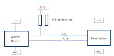
 I2C Communication: This post rewind the I2C Hardware overview, I2C Pullup resistor value calculation, and LT Spice simulation. Hardware Overview: The I2C bus is a very popular and simple bus used for communication between a master or multiple masters and single or multiple slave devices.  This communication only uses two-wire SDA and SCL. Which is a serial data line and serial clock line.  Both SCL and SDA lines are open-drain or open-collector configurations. This means it needs an external pullup resistor is completely taking control of generating the logic high signal. I2C uses an 8-bit data structure which is a common data format for most Microcontroller and Microprocessor In the 8 bit communication, 7 bits are address bits and the last bit represents the Read/Write operation (1=Read Write =0) I2C Protocol is address-based, meaning that all the slave IC must have a unique address, this address is configured through hardware pins to logic "1" or "0". Some slaves...

555 Timer Astable mode, Lt spice simulation, and real-time testing

Image
555 Timer Astable mode, Lt spice simulation, and real-time testing  We know 555 timer has three operating modes called Astable mode, Monostable mode, and Bistable mode. Astable Mode : In Astable mode, 555 IC will act as an oscillator that generates a square wave  continuously .  The frequency of the wave can be adjusted by changing the values of two resistors and a capacitor connected to the chip.   LTspice circuit: Formulas: Calculations: Ton = 0.693(1k+100k)22uF =1.539ms Toff =0.693*100k*22uF =1.524ms T = Ton + Toff  = 0.693(1K+2*100k)22ufF=3.064ms  Frequency  = 1/T = 1.44/(1k+2*100k)22uF = 1/3.06ms =0.3263Hz Duty = 50.2% Simulation Results: Click here to download the Astable mode LTspice circuit Testing: