Automotive Ethernet Interface Basics:
BLOCK DIAGRAM :

MDI (Media Dependent Interface):
MDI defines how signals are transmitted and received over Ethernet cables, especially in automotive networks using Single-Pair Ethernet
PHY (Physical Layer) Chip: The signal from the PHY chip is transmitted over twisted-pair cables.
DC Blocking / AC Coupling Capacitor: Placed in series between the PHY and the Ethernet cable to block any DC bias and protect the system. AC Coupling is realized by 100nF Coupling Capacitor to form a high pass filter together with 50Ohm termination on each line.
Signal Integrity: The capacitor ensures that only the desired AC signal (which carries data) is passed to the PHY, while any DC bias is blocked.
CMC (Common Mode Choke) is used to reduce electromagnetic interference and noise, ensuring reliable data transmission in noisy automotive environments.
Common mode Termination :
For common-mode termination, a split termination consisting of two 1kΩ resistors and a 4.7nF capacitor, with a 100 kΩ resistor to GND, can be connected to the signal lines between the coupling capacitors and the connector. For reasons of symmetry, the tolerance of the two 1 kΩ resistors should be within ±1 %. The power rating should be higher than 0.4 W (anti-surge) in order to survive EMI disturbances. They match the impedance of the Ethernet cable, prevent signal reflections, and ensure that the data stays accurate. Those are not be shown in the image above.
| Automotive Ethernet Standard | IEEE Standard | Speed | Media | Use Case |
|---|---|---|---|---|
| 100BASE-T1 | IEEE 802.3bw | 100 Mbps | Single-Pair Ethernet (SPE) | Low-speed applications (e.g., sensors, body control modules) |
| 1000BASE-T1 | IEEE 802.3bp | 1 Gbps | Single-Pair Ethernet (SPE) | Infotainment, ADAS, high-speed sensor networks |
| 10GBASE-T1 | IEEE 802.3bm | 10 Gbps | Single-Pair Ethernet (SPE) | High-performance applications, autonomous vehicles, HD video |
| 10BASE-T1S | IEEE 802.3cg | 10 Mbps | Single-Pair Ethernet (SPE) | Low-bandwidth applications, diagnostic communication |
| 10BASE-T1L | IEEE 802.3cg | 10 Mbps | Single-Pair Ethernet (SPE) | Long-reach applications, energy management in EVs |
In these standards, T1 refers to a single twisted pair Ethernet media, and the numbers indicate the speed:
- 100BASE-T1: 100 Mbps
- 1000BASE-T1: 1 Gbps
- 10GBASE-T1: 10 Gbps
The S and L denote short and long-range capabilities, with S supporting up to 25 meters for low-speed data transfer and L supporting up to 1000 meters for industrial applications.
Clock Frequency :
In Automotive Ethernet, the PHY’s clock frequency depends on the Ethernet standard and application:
For 1000BASE-T1, a 125 MHz clock is commonly used.
A crystal oscillator generates the stable clock, sometimes using lower frequencies (e.g., 25 MHz or 50 MHz) to feed into a Phase-Locked Loop (PLL) that multiplies the frequency to achieve the required clock rate.
For example, to transmit 1 Gbps data over Automotive Ethernet using a 25 MHz clock, the clock is typically used to generate timing and encoding signals necessary for high-speed data transmission.

Example:
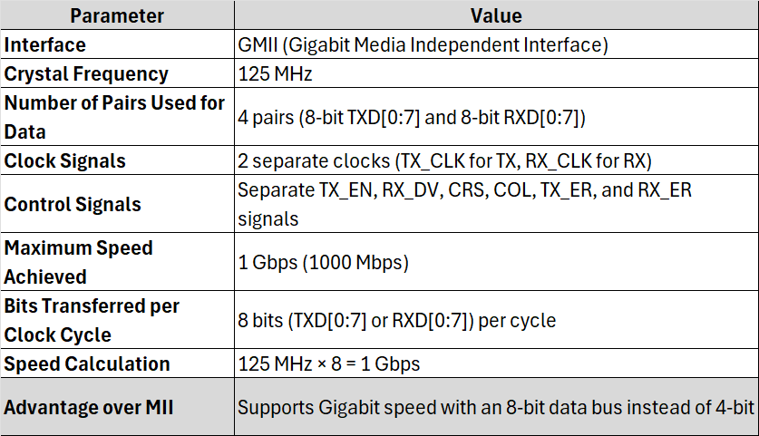
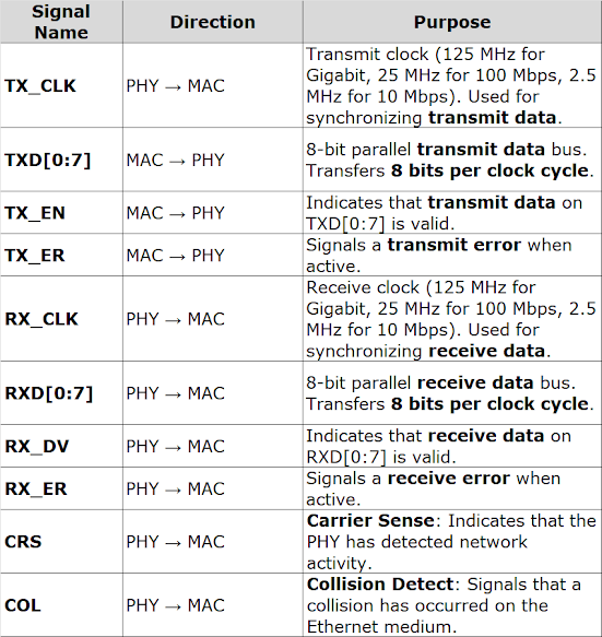
MII (Media Independent Interface):


RMII (Reduced Media Independent Interface) :

MII vs. RMII Pin Count Reduction


RGMII (Reduced Gigabit Media Independent Interface):


SGMII (Serial Gigabit Media Independent Interface):

Number of Pairs Used: SGMII uses 2 pairs (Tx+/−, Rx+/−) for data transmission.
SGMII Data Rate Calculation with 8b/10b Encoding
SGMII operates at 1 Gbps Ethernet, but due to 8b/10b encoding overhead, the actual serial data rate is:
The extra 250 Mbps is used for encoding overhead.
Why Encoding is Needed in SGMII?
Since SGMII is a high-speed serial interface (1.25 Gbps), it needs encoding to:
- Maintain DC balance – Ensures equal numbers of 1s and 0s to avoid signal bias.
- Enable clock recovery – Embeds clock information into the data stream, eliminating the need for a separate clock signal.
- Improve error detection – Detects invalid data sequences and transmission errors.
How 8b/10b Encoding Works in SGMII
- Each 8-bit data byte is converted into a 10-bit codeword before transmission.
- The extra 2 bits help in DC balance, clock synchronization, and error detection.
- The receiver decodes the 10-bit data back into 8-bit data.


Data inside the Ethernet PHY or MAC is handled in parallel format.
For 1 Gbps Ethernet, 8 bits of data are transferred per clock cycle between the MAC and PHY.
The clock speed at this stage is 125 MHz
125MHz×8bits per clock cycle=1Gbps
So, 125 MHz is the clock frequency used for parallel data transfers (internal to MAC/PHY).
Serial Data Stage (Over the SGMII Link)
Over the SGMII serial interface, the data is serialized, requiring a much higher clock frequency (625Mhz) to maintain the same data rate (1 Gbps with 8b/10b encoding).
Why 625 MHz in the Serial Stage?
The serial data on the SGMII link uses 8b/10b encoding, meaning every 8 bits of data becomes 10 bits on the wire. This increases the line rate by 25%:
1Gbps (data rate)×1.25=1.25Gbps (raw line rate).
In serialized mode:
1 clock cycle transmits 2 bits of serialized data.
To achieve the 1.25 Gbps raw line rate, the clock frequency is:
Clock Frequency= Raw Line Rate / Bits Per Clock Cycle =1.25Gbps/2 =625Mhz
Why Encoding Matters in SGMII ?
Clock Recovery:
- In serial interfaces like SGMII, the clock signal is not transmitted as a separate signal (unlike parallel interfaces, which have a dedicated clock line). Instead, the clock is embedded in the data stream.
- Encoding schemes like 8b/10b introduce transitions in the signal to ensure sufficient edges (transitions from high to low or low to high) for the receiver to recover the clock from the data stream.
High-speed serial transmission requires a balanced DC component to avoid signal degradation caused by too many consecutive 1s or 0s.
8b/10b encoding ensures DC balance by mapping 8-bit data to 10-bit symbols, which are carefully designed to maintain equal numbers of 1s and 0s.
Error Detection:
Encoding adds redundancy to the data stream, enabling basic error detection at the physical layer.
In SGMII, this redundancy helps ensure that any errors in transmission (caused by noise, interference, etc.) can be identified and handled.
Encoding Techniques:
- NRZ/PAM2 (Non-Return to Zero / Pulse Amplitude Modulation 2 levels)
- PAM3
- PAM4
- PAM5
These encoding techniques are used to manage the signaling, data transfer rates, and overall performance of high-speed Ethernet in automotive applications.
PAM3 EXAMPLE:
Three Amplitude Levels:
- PAM-3 uses three distinct voltage levels (or amplitudes) to represent data.
- For example, the levels could be: -V, 0, and +V, where:
- -V represents a logical 0,
- 0 represents a neutral or idle state (often used for synchronization or control),
- +V represents a logical 1.
How PAM-3 Works:
- In PAM-3, each symbol (group of bits) is encoded using three levels. This allows more information to be transmitted per symbol compared to binary encoding, where only two levels (e.g., 0 and 1) are used.
- A single PAM-3 symbol can represent 2 bits of information:
- Level -V could represent 00,
- Level 0 could represent 01,
- Level +V could represent 10.
TC10 is an automotive Ethernet standard that defines a sleep mode and wake-up mechanism
TC10 defines PHY current consumption to be less than 35 microamps while in TC10 sleep. These sleep requests and wake-up pulses are exchanged over the Ethernet cable without needing a dedicated wakeup wire. These sleep requests will be initiated by the Ethernet MAC using software registers.
The PHY can then be woken up by two methods.
1. Local Wakeup
2.Remote Wakeup


No comments:
Post a Comment