PWM SOLAR CHARGE CONTROLLER USING PIC16F877A
What is a Charge Controller ?
A solar charge controller regulates the voltage and current coming from your solar panels which is placed between a solar panel and a battery .It is used to maintain the proper charging voltage on the batteries. As the input voltage from the solar panel rises, the charge controller regulates the charge to the batteries preventing any over charging.
Types of Charge controller :
1.ON OFF
2. PWM
3. MPPT
The most basic charge controller(ON/OFF type) simply monitors the battery voltage and opens the circuit, stopping the charging, when the battery voltage rises to a certain level.
Among the 3 charge controllers MPPT have highest efficiency but it is costly and need complex circuits and algorithm.
What is PWM:
Pulse Width Modulation (PWM) is the most effective means to achieve constant voltage battery charging by adjusting the duty ratio of the switches ( MOSFET ). In PWM charge controller, the current from the solar panel tapers according to the battery’s condition and recharging needs. When a battery voltage reaches the regulation set point, the PWM algorithm slowly reduces the charging current to avoid heating and gassing of the battery, yet the charging continues to return the maximum amount of energy to the battery in the shortest time.
Advantages of PWM charge controller :
1. Higher charging efficiency
2. Longer battery life
3. Reduce battery over heating
4. Minimizes stress on the battery
Voltage Divider Network
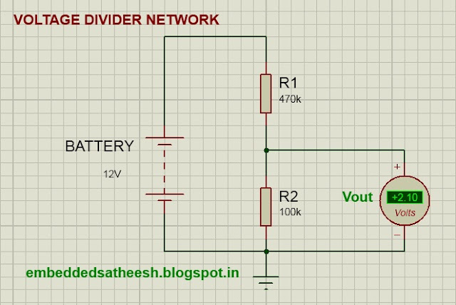
As the PIC microcontroller analog pin input voltage is restricted to 5V, I designed the voltage divider in such a way that the output voltage from it should be less than 5V. I used a 6W (Voc=10v)solar panel and a 6v battery for storing the power .So I have to step down both the voltage to lower than 5V.
I used R1=470k and R2 =100K in sensing both the voltages(solar panel voltage and battery voltage).
Calculations:
let the battery voltage is 6V
Vout = 100/(470+100)*12= 1.05v
Both Solar and Battery voltages from voltage dividers are lower than 5v and suitable for PIC16F AN0 analog pin
VOLTAGE DIVIDER NETWORK CIRCUIT:
 |
| Figure 1: Voltage divider network |
PWM Circuit:
PWM (pulse width modulation) is a technique by which we simply control a digital output signal by switching it on and off very quickly, by varying the width of the on/off duration, it will give the effect of varying the output voltage.
We are going to use 60Hz frequency for charging the battery
MOSFETs:
In this charge controller I used two MOSFETs one is for controlling the power flow from solar panel to battery and other is to drive the load.When I started working with MOSFET ,little bit confused how to select a right one.After reading so many forum I found that it is so easy.I think any one can choose the MOSFET by using few guidelines.These are the few important parameters which you will need during choosing a right MOSFET.
1. N or p channel :
when a MOSFET is connected to ground and the load is connected to supply voltage, it is considered to be a low-side switch. In a low-side switch, an n-channel device is used.In my charge controller I used IRF 540 for driving the load.
A high-side switch is used when the MOSFET is connected to the supply voltage and the load is connected to ground. A p-channel MOSFET is usually used in this topology .I used IRF 9530 as the main switching MOSFET for PWM.
See the schematics how load is connected in both the cases.
2. Drain Source Voltage Vds :
When the MOSFET is turned off, the whole supply voltage will be measurable across it, so this rating should be larger than your supply voltage to provide sufficient protection so that the MOSFET does not fail. The maximum voltage a MOSFET can handle varies with temperature.
3.Continuous Drain Current Ids :
This is the amount of current the MOSFET can handle.You need to simply select the device that can handle the maximum amount of current including surges or "peaks".Current rating also decreases with rise in temperature.
So keep sufficient margin in Ids.It is better to take current rating @ 125deg Cel.
4. RDS(on) :
When a MOSFET is "on," it acts as a variable resistor determined by the RDS(on) that changes with temperature with a power dissipation calculated by Iload2 x RDS(on). So choose a MOSFET with smaller value of RDS(on).
5. Thermal Loss:
It can be found from datasheets : the maximum junction temperature and the thermal resistance from junction-to-ambient for the package. The device's junction temperature is equal to the maximum ambient temperature plus the product of the thermal resistance and the power dissipation (Junction Temperature = Maximum Ambient Temperature + (Thermal Resistance x Power Dissipation) ).
6. Gate Threshold Voltage VGS(th) :
This is the minimum voltage required between the gate and source terminals to turn the MOSFET on. It will need more than this to turn it fully on.
MOSFET DRIVER:
 |
| Figure2: Mosfet driver |
Protection :
Protections are provided in the charge controller to protect against extreme and abnormal operating condition.
In commercial charge controller there are so many protection.But in my charge controller all are not included.
Following protection are used :
Over Voltage Protection:
During lightening and thundering over voltage occurs in the system.To protect the system a zener diode is used.
I used a 11V zener diode as my solar panel open circuit voltage is 10v. When the voltage is more than 11v ,it will provide the ground path to the surges.
Protection to over current :
Two fuses F1 and F2 are used for over current protection.One is at the incoming side i.e after the solar panel and other is before the load. I forgot to show in the first schematics.
Refer my updated schematics where I put the fuses.
PV panel reverse current :
During night battery voltage is higher in compare to solar panel voltage(0 V).So power can be flow in the reverse direction .This avoided by using a diode(D1) after the solar panel.
Auto Load Disconnection :
To avoid deep discharging of battery ,auto load disconnection scheme is implemented through the software.When the battery voltage is falls below a certain voltage (6.2V)load is automatically disconnected.
Overcharge protection :
Over charge protection is given to improve the battery life and prevent from overheating .When the battery voltage is greater than the fully charged voltage(7.2v) ,it is disconnected from the solar panel to avoid further charging.This is also implemented through the software.
 |
| Figure 3: PWM Charger circuit |
Software and PCB design coming Soon...


I was having trouble purchasing Solar charge controller price in pakistan for my home but this article helped me. Thank you for sharing.
ReplyDeleteHappy to see your reply...
ReplyDelete